Posted on January 24, 2015
The purpose of this testing was to evaluate the effectiveness of a hybrid fire suppression system on aeroderivative style gas turbines. A utility company and its fire protection engineer provided the use of a Pratt & Whitney FT4 aeroderivative turbine generator to test the hybrid inert gas/water mist system on an operating unit under load, enabling the research team to assess the system’s efficacy in real-world scenarios.
The utility company established the test criteria: Testing would be deemed successful if the system could cool the turbine skin to less than 380°F within 10 minutes. 380°F represents the auto ignition temperature (AIT) of lube oil and turbine fuel, plus a safety factor. The 10-minute timeframe was established to match the performance of the existing CO2 extinguishing system.
A series of tests was devised to demonstrate the suppression system’s effectiveness for cooling. The tests involved operating the turbine off the power grid but at full speed, on the power grid and allowing the unit to cool naturally as well as on the grid and allowing the system to discharge. Systematic changes in water flow and installation parameters were used to find optimal results.
Background
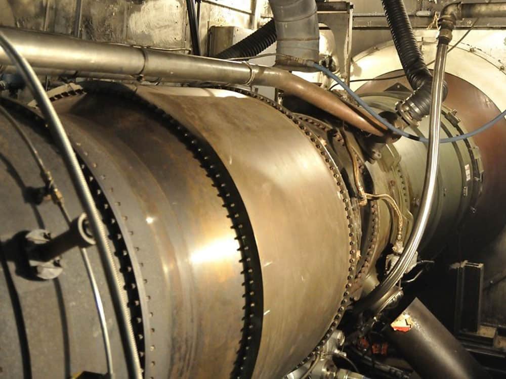
Testing was conducted at a site in Holtsville, New York, housing 10 twin pack FT4 aeroderivative turbines. Each pack consists of a generator and two FT4 aircraft turbines at each end. The thrust of each turbine engine is directed through a “free turbine” that is on the same shaft as the generator. The turbine generators are used to generate electricity during peak demands. Each twin pack is capable of producing electricity on the grid in just over 2 minutes, and can provide full capacity—approximately 50 MW—within 8 minutes of startup. Upon shutdown, the turbine is no longer producing thrust, however the independent “free turbine” and generator shaft continues to rotate for 20 minutes until it coasts to a stop.
The FT4 enclosures create a challenge in that the rear exhaust portion is not sealed and is open to the atmosphere. The thrust exiting the free turbine entrains the air within the enclosure. The entrained air enters the enclosure through secondary dampers and provides cooling for the turbine enclosure when operating. Upon detection of a fire, the turbine generator is shut down, which involves the unit being immediately removed from the grid, the fuel shut down, and secondary air dampers closed, limiting the airflow through the enclosure.
Fires in turbine enclosures are generally caused by a leak or failure of a fuel or lube oil line. If a fitting loosens or the hose breaks, the media could pool or spray onto a hot surface, igniting the fluid. Although the fuel line can be shut down upon detection of a fire, the lube oil must continue to circulate until the free turbine and generator stop rotating. As a result, fire suppression systems should be able to extinguish the fire as well as quickly and uniformly cool the turbine skin to prevent re-ignition of the lube oil or turbine fuel. Non-uniform cooling can cause warping of the turbine skin, which could impact the blades.
FM requirements for CO2 fire suppression systems are to provide a design concentration of 34% within 1 minute and maintain 30% for a period of 20 minutes or 10 minutes plus the time needed for a safe shut down of the lube oil. This is because such systems don’t provide cooling, so volumes of the suppressing agent must be sustained at levels unable to support combustion. During CO2 system testing at the Holtsville site, it took 10 minutes to reduce the temperature of the turbine skin below the auto ignition temperature.
Hybrid fire suppression systems are a newer option for the protection of turbine enclosures. They offer advantages over CO2 systems, including the elimination of life safety and enclosure integrity concerns. A hybrid system employs water and an inert gas to suppress a fire. The gas essentially atomizes the water, creating a swirling fog in the enclosure. The components attack the fire simultaneously, the water cooling the space and the gas reducing the oxygen content and generating steam.
Hybrid systems produce water droplets that are smaller than 10 microns in size—up to 100 times smaller than water particles delivered through traditional water mist systems. The small droplet size combined with the minimal amount of water released per emitter prevents significant wetting in the space.
Methods
A total of 8 tests were used to evaluate the cooling performance of the hybrid fire suppression system.
- Turbine unit operated at full speed without load, not connected to the grid.
- Turbine unit operated at base load, connected to the grid for no less than 5 minutes.
- Turbine unit operated at base load, connected to the grid for no less than 5 minutes.
- Turbine unit operated at base load, connected to the grid for no less than 5 minutes. Unit tripped, secondary dampers shut. Hybrid fire suppression system operated using 2 emitters projected toward the compressor end. 1⁄2” emitters at 25 psig, flowing 0.26 GPM of water each.
- Turbine unit operated at base load, connected to the grid for no less than 5 minutes. Unit tripped, secondary dampers shut. Hybrid fire suppression system operated using 2 emitters projected toward the floor under the combustion cam section. 1⁄2” emitters at 25 psig, flowing 0.26 GPM of water each.
- Turbine unit operated at base load, connected to the grid for no less than 5 minutes. Unit tripped, secondary dampers shut. Hybrid fire suppression system operated using 2 emitters projected toward the floor under the combustion cam section. 1⁄2” emitters at 25 psig, flowing 0.79 GPM of water each.
- Turbine unit operated at base load, connected to the grid for no less than 5 minutes. Unit tripped, secondary dampers shut. Hybrid fire suppression system operated using 2 emitters projected toward the hot section, aft the combustion cam, to distribute maximum quantity of mist. 1⁄2” emitters at 25 psig, flowing 1.06 GPM of water each.
- Turbine unit operated at base load, connected to the grid for no less than 5 minutes. Unit tripped, secondary dampers left open. Hybrid fire suppression system operated using 2 emitters projected toward the hot section, aft the combustion cam, to distribute maximum quantity of mist. 1⁄2” emitters at 25 psig, flowing 1.06 GPM of water each.
Installation
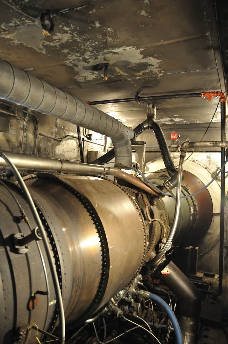
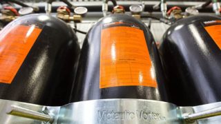
Per FM Approval Standard 5580, 2 emitters were installed in the turbine enclosure based on the enclosure volume (figures 1 and 2). The test apparatus involved a 60-gallon water tank to be pressurized using the outlet pressure of the hybrid fire suppression system automatic regulating valve (ARV). A 20-port manifold was connected to 20 49-liter nitrogen cylinders. One end of the manifold had the fire suppression system ARV while the other end was connected to a tube trailer using a high-pressure (3,000 psi) hose. The tube trailer consisted of 62,000 cubic feet of nitrogen at approximately 2,700 psi and was used to refill the cylinders between testing.
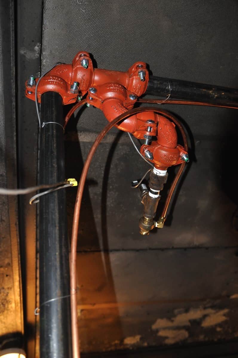
The fire suppression system ARV was programmed for a 10-minute continuous discharge. To increase the ease of installation and testing, set valued water flow cartridges were utilized. Copper compression tubing measuring 3/8” outer diameter was used to supply the water from the flow cartridge to each emitter. 1-1/2” schedule 10 piping was roll grooved and used to supply the nitrogen to the emitters.
Instrumentation
A National Instruments data acquisition system was used to record temperatures at the compressor section, combustion section front, combustion section rear, hot turbine section, exhaust diffuser, enclosure, as well as oxygen level under the unit near the fuel hose connections. In addition to data being collected from the National Instruments unit, hand held devices were used to record outside air temperature, relative humidity as well as air flow through the secondary dampers.
Results
Test #1
The turbine was operated at full speed but without a load being applied by the electrical grid. Outside the enclosure, the air temperature measured 44°F with a relative humidity of 34.6.
| Maximum Temperature, °F | Minimum Temperature, °F | |
| Compressor Section | 64.04 | 47.87 |
| Enclosure Temperature | 97.28 | 52.09 |
| Combustion Section Front | 202.32 | 53.38 |
| Combustion Section Rear | 251.89 | 54.48 |
| Exhaust Section | 301.15 | 53.61 |
Air velocities through the two secondary dampers were recorded at a rate of 825 FPM. Each secondary damper measured 27-3/4” x 73”, thus providing a volume of 23,212 cubic feet per minute of compartment air exchange.
Data was collected for a period of 46 minutes, monitoring the natural cool down of the unit. During the tests, the temperatures did not exceed the auto ignition temperature of 410°F or the target maximum temperature of 380°F.
Test #2
The turbine unit was operated at base load, 50 MW, and remained on the electrical grid for approximately 13 minutes before being tripped off. Outside the enclosure, the air temperature measured 52°F with a relative humidity of 35.
| Maximum Temperature, °F | Minimum Temperature, °F | |
| Compressor Section | 74.09 | 57.21 |
| Enclosure Temperature | 139.24 | 71.63 |
| Combustion Section Front | 397.83 | 76.79 |
| Combustion Section Rear | 406.99 | 116.32 |
| Exhaust Section | 578.61 | 185.73 |
Air velocities through the two secondary dampers traveled at a rate of 2,148 FPM, thus providing a volume of 60,434 cubic feet per minute of compartment air exchange.
Data was collected for a period of 42 minutes, monitoring the natural cool down of the unit. During the tests, the temperature exceeded the AIT of 410°F. The unit cooled below AIT after a period of 17:16 after being tripped and shut down. The exhaust section remained above the target maximum temperature of 380°F for a period of 23 minutes.
Test #3
The turbine unit was operated at base load, 49 MW, and remained on the electrical grid for approximately 13 minutes before being tripped off. Outside the enclosure, the air temperature measured 60°F with a relative humidity of 33.8.
| Maximum Temperature, °F | Minimum Temperature, °F | |
| Compressor Section | 79.93 | 66.29 |
| Enclosure Temperature | 145.60 | 83.39 |
| Combustion Section Front | 382.08 | 108.77 |
| Combustion Section Rear | 407.68 | 178.90 |
| Exhaust Section | 554.61 | 135.49 |
| Hot Section | 694.83 | 314.73 |
Data was collected for a period of 32 minutes, monitoring the natural cool down of the unit (figure 3). During the tests, the temperature exceeded the AIT of 410°F. The hot section of the turbine cooled below 380°F after a period of 18:35 after being tripped and shut down. The exhaust section remained above 380°F for the 32-minute period.
click to zoom
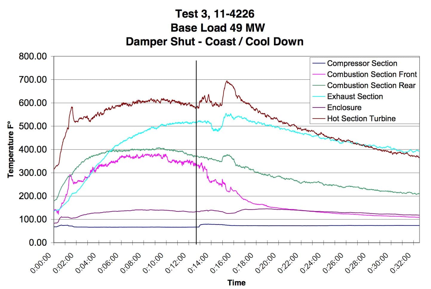
Figure 3: Test #3 results, monitoring the natural cool down of the unit.
Test #4
The turbine unit was operated at base load, 49.5 MW, and remained on the grid for 11 minutes. The unit was tripped, secondary dampers shut and the hybrid fire suppression system with emitters projected toward the compressor end began to discharge. The emitters, flowing 0.26 GPM of water each, operated for a period of 10 minutes, discharging a total of 5 gallons of water into the enclosure. Outside the enclosure, the air temperature measured 63°F with a relative humidity of 37.7.
| Maximum Temperature, °F | Minimum Temperature, °F | |
| Compressor Section | 79.81 | 61.73 |
| Enclosure Temperature | 204.82 | 64.71 |
| Combustion Section Front | 380.29 | 66.06 |
| Combustion Section Rear | 484.59 | 69.08 |
| Exhaust Section | 604.99 | 64.71 |
| Hot Section | 751.91 | 68.52 |
Data was collected for a period of 24 minutes, monitoring the startup through end of discharge of the hybrid fire suppression system. During the tests, the temperatures exceeded the AIT of 410°F. Following discharge, neither the hot section of the turbine or exhaust section cooled below 380°F. The enclosure door was opened for viewing purposes and the fire suppression system discharged. It was noted that the discharge remained at the front of the unit as it dissipated.
Test #5
The turbine unit was operated at base load, 47 MW, and remained on the grid for 10 minutes and 30 seconds. The unit was tripped, secondary dampers shut and the hybrid fire suppression system with emitters projected toward the floor under the combustion cam section began to discharge. The emitters, flowing 0.26 GPM of water each, operated for a period of 10 minutes, discharging a total of 5 gallons of water into the enclosure. Outside the enclosure, the air temperature measured 70°F with a relative humidity of 36.2.
| Maximum Temperature, °F | Minimum Temperature, °F | |
| Compressor Section | 87.59 | 71.05 |
| Enclosure Temperature | 193.07 | 78.89 |
| Combustion Section Front | 392.83 | 89.66 |
| Combustion Section Rear | 465.76 | 108.13 |
| Exhaust Section | 595.76 | 115.13 |
| Hot Section | 906.77 | 114.20 |
Data was collected for a period of 25 minutes, monitoring the startup through end of discharge of the hybrid fire suppression system. During the tests, the temperatures exceeded the AIT of 410°F. Post discharge, neither the hot section of the turbine or exhaust section cooled below 380°F. The enclosure door was opened for viewing purposes and the fire suppression system discharged. It was noted that the mist remained in the area of discharge and it dissipated quickly. Oxygen levels under the rear of the compressor section during the discharge were found to average 18%.
Test #6
The turbine unit was operated at base load, 51 MW, and remained on the grid for 12 minutes. The unit was tripped, secondary dampers shut and the hybrid fire suppression system with emitters projected toward the floor under the combustion cam section began to discharge. The emitters, flowing 0.8 GPM of water each, operated for a period of 10 minutes, discharging a total of 16 gallons of water into the enclosure. Outside the enclosure, the air temperature measured 60°F with a relative humidity of 37.
| Maximum Temperature, °F | Minimum Temperature, °F | |
| Compressor Section | 73.74 | 60.99 |
| Enclosure Temperature | 185.07 | 76.57 |
| Combustion Section Front | 403.78 | 78.84 |
| Combustion Section Rear | 451.66 | 125.35 |
| Exhaust Section | 599.45 | 165.44 |
| Hot Section | 907.88 | 206.60 |
Data was collected for a period of 26 minutes, monitoring the startup through end of discharge of the hybrid fire suppression system. During the tests, the temperatures exceeded the AIT of 410°F. Post discharge, neither the hot section of the turbine or exhaust section cooled below 380°F. The enclosure door was opened for viewing purposes and the fire suppression system discharged. It was noted that the mist created puddles in the area of discharge and was observed by utility personnel to be wetter, localized, than anticipated. Oxygen levels under the rear of the compressor section during the discharge were found to average 18%.
Test #7
The turbine unit was operated at base load, 47 MW, and remained on the grid for 11 minutes. The unit was tripped and secondary dampers shut. The hybrid fire suppression system with emitters projected toward the hot section, aft the combustion cam, to distribute maximum quantity of mist began to discharge. The emitters, flowing 1.06 GPM of water each, operated for a period of 10 minutes, discharging a total of 21 gallons of water into the enclosure. Outside the enclosure, the air temperature measured 60°F with a relative humidity of 37.
| Maximum Temperature, °F | Minimum Temperature, °F | |
| Compressor Section | 73.74 | 60.99 |
| Enclosure Temperature | 185.07 | 76.57 |
| Combustion Section Front | 403.78 | 78.84 |
| Combustion Section Rear | 451.66 | 125.35 |
| Exhaust Section | 599.45 | 165.44 |
| Hot Section | 907.88 | 206.60 |
Data was collected for a period of 33 minutes, monitoring the startup of the turbine through end of discharge of the hybrid fire suppression system. During the operation of the unit, the temperatures exceeded the AIT of 410°F. The hot section of the turbine cooled to less than 380°F in 20 seconds, followed by the exhaust section in 43 seconds and the combustion section rear in 56 seconds. At the end of the 33 minutes, the enclosure door was opened and utility personnel noted very little wetting and cooler temperatures for both the turbine and inside the enclosure. No appreciable decrease in oxygen was observed, averaging 20% during the discharge.
Test #8
The turbine unit was operated at base load, 46 MW, and remained on the grid for 9 minutes. The unit was tripped, secondary dampers were left open and the hybrid fire suppression system with emitters projected toward the hot section, aft the combustion cam, to distribute maximum quantity of mist began to discharge. The emitters, flowing 1.06 GPM of water each, operated for a period of 10 minutes, discharging a total of 21 gallons of water into the enclosure. Outside the enclosure, the air temperature measured 63°F with a relative humidity of 39.
| Maximum Temperature, °F | Minimum Temperature, °F | |
| Compressor Section | 78.62 | 65.98 |
| Enclosure Temperature | 146.59 | 71.15 |
| Combustion Section Front | 383.28 | 81.77 |
| Combustion Section Rear | 443.60 | 101.93 |
| Exhaust Section | 502.33 | 95.52 |
| Hot Section | 790.17 | 98.16 |
Data was collected for a period of 34 minutes, monitoring the temperatures from the startup of the turbine through end of discharge of the hybrid fire suppression system (figure 4). During the operation of the turbine, the temperatures exceeded the AIT of 410°F. With the fire suppression system discharging, the combustion section rear cooled to less than 380°F in 13 seconds followed by hot section of the turbine in 18 seconds and the exhaust section in 33 seconds. At the end of the 34 minutes, the enclosure door was opened and utility personnel again noted very little wetting and cooler temperatures for both the turbine and inside the enclosure. No appreciable decrease in oxygen was observed, averaging 20.5% during the discharge.
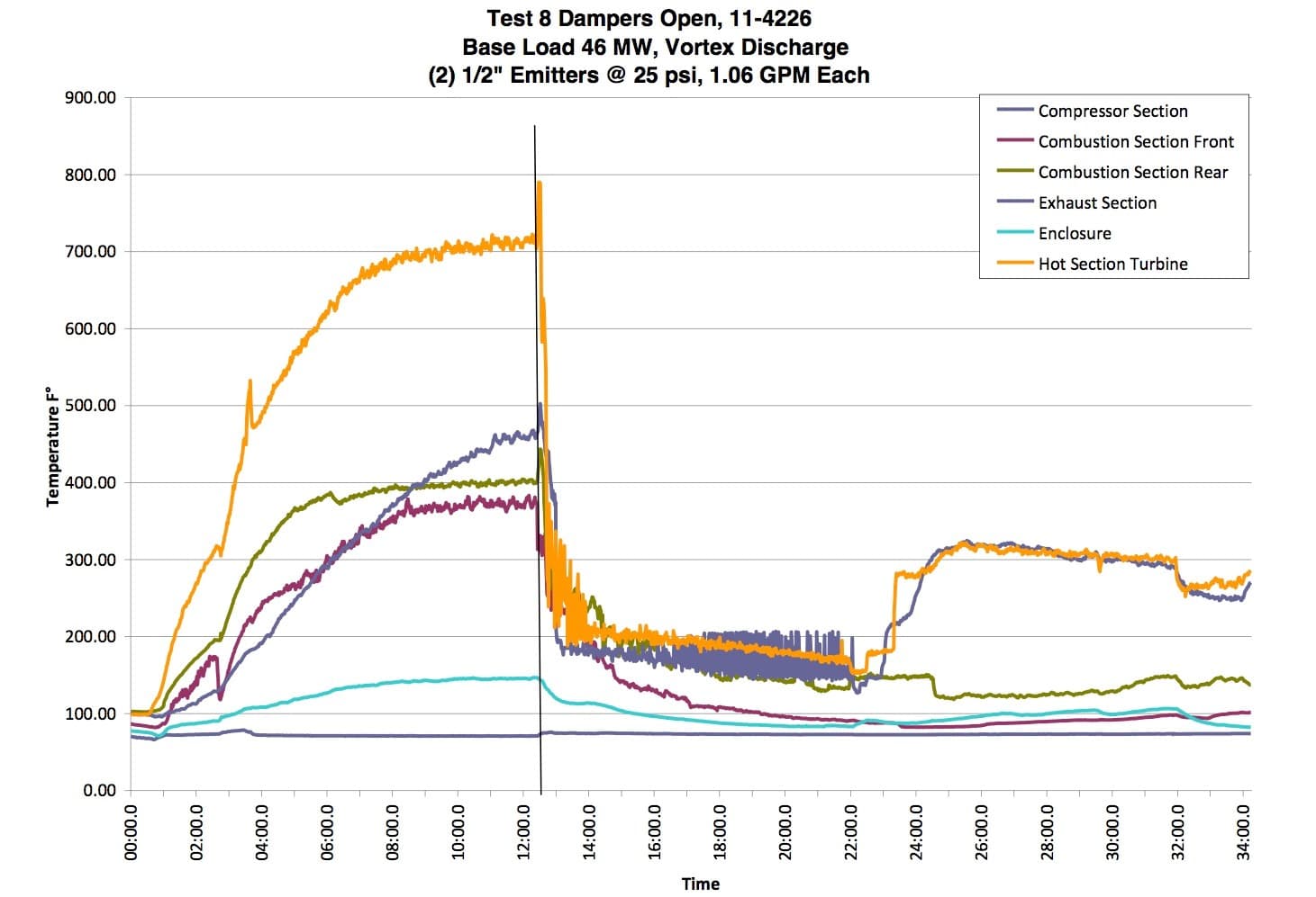
click to zoom
Figure 4: Test #8 results: Combustion section rear cooled to less than 380°F in 13 seconds, hot section in 18 seconds and exhaust section in 33 seconds.
Conclusions
The testing concluded with the FT4 turbine and generator at base load and full operating temperature. The hybrid fire suppression system met the criteria established by the utility, that is, to cool the turbine skin to below 380°F within 10 minutes. Test #8 showed that it was capable of doing so within 33 seconds.
Successful cooling results were obtained with the emitters installed overhead and aimed toward the hot section of the turbine. However, the turbine body becomes an obstruction and reduces the velocity of the discharge below the turbine body where the fuel lines can reside. The design of the enclosure with an open exhaust plenum adds difficulty in that oxygen reduction, as shown in the results of the testing, is minimal. To resolve the obstruction and provide a more uniform discharge around the turbine, it is recommended that additional nozzle(s) be installed below the turbine. The additional emitters add cooling and fire suppression to protect the underside of the turbine, thus mirroring the overhead protection.
The results of this testing indicate that hybrid fire suppression systems are able to adequately protect aeroderivative turbines under normal operating conditions. The testing offers a proof point that such systems are not damaging to equipment, overcoming historic objections to the use of water-mist-style systems on such turbines for fear of damage. Hybrid fire suppression systems are a viable, significant alternative to CO2 systems for the protection of aeroderivative style gas turbines.
About the Author
Bob Ballard is the Fire Suppression Technology Manager at Victaulic, a manufacturer of mechanical pipe-joining and fire protection systems. Bob has 20 years of research and development experience in the field of fire protection. In 2003, he joined Victaulic and began developing the special hazard hybrid fire suppression system Victaulic Vortex™. Bob is a technical committee member for the following groups: NFPA 75 Standard for the Fire Protection of Information Technology Equipment, NFPA 318 Committee on Semiconductor and Related Facilities, NFPA 750 Water Mist Fire Suppression Systems.